
01
Mold Design
According to product structure and performance requirements, conduct 3D modeling and structural design of the mold.
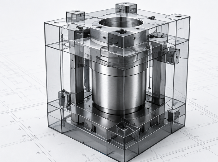
Mold design is crucial in the production process of amorphous alloys, and precision molds determine the performance and quality of amorphous alloy products.
Amorphous alloys (Amorphous Alloy / Bulk Metallic Glass, abbreviated as BMG) are widely used in high-end fields such as aerospace, medical devices, consumer electronics, precision machinery, and high-end sports equipment due to their high strength, high elasticity, corrosion resistance, wear resistance, and excellent forming performance.
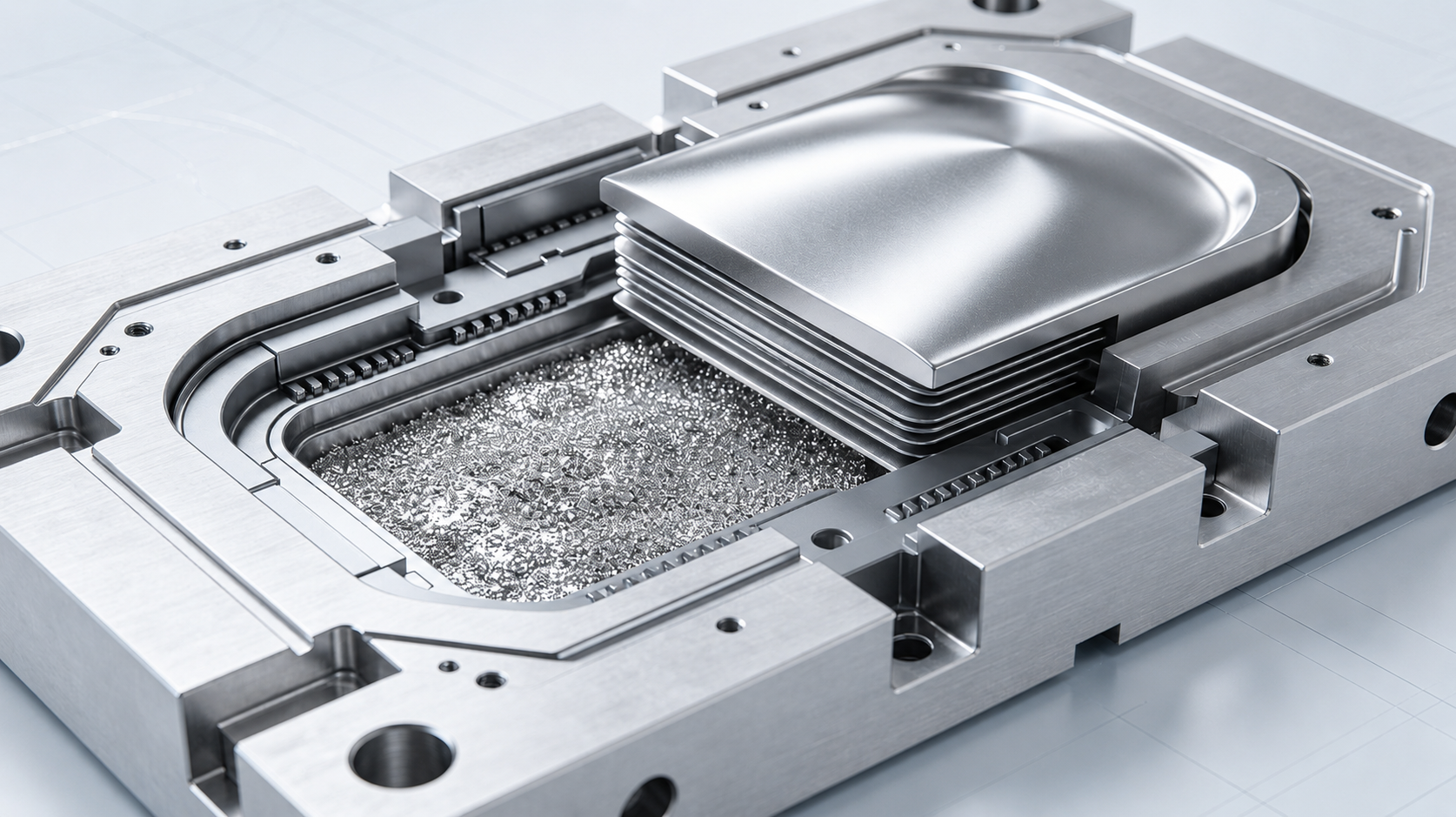
In the production process of amorphous alloys, one of the key factors that truly determines product quality stability and yield is the design and manufacturing precision of the mold.
Since amorphous alloys need to complete rapid cooling in a very short time and maintain an amorphous structure, there are extremely high requirements for the mold's thermal conductivity, dimensional accuracy, structural stability, and surface quality.
The mold is not only a forming tool, but also the core technical foundation affecting amorphous formation, product consistency, and production efficiency.
Amorphous alloys (metallic glasses) possess excellent properties such as high strength, high elasticity, and corrosion resistance. However, their forming process requires extremely high cooling rates (typically 10³–10⁶ K/s), and their fluidity and shrinkage behavior are entirely different from traditional metals.
From mold design and material selection to precision machining, assembly, and final validation, each stage is controlled to ensure accuracy, durability, and stable forming performance.
According to product structure and performance requirements, conduct 3D modeling and structural design of the mold.
Select high-purity amorphous alloy master material to ensure uniform composition and stable performance.
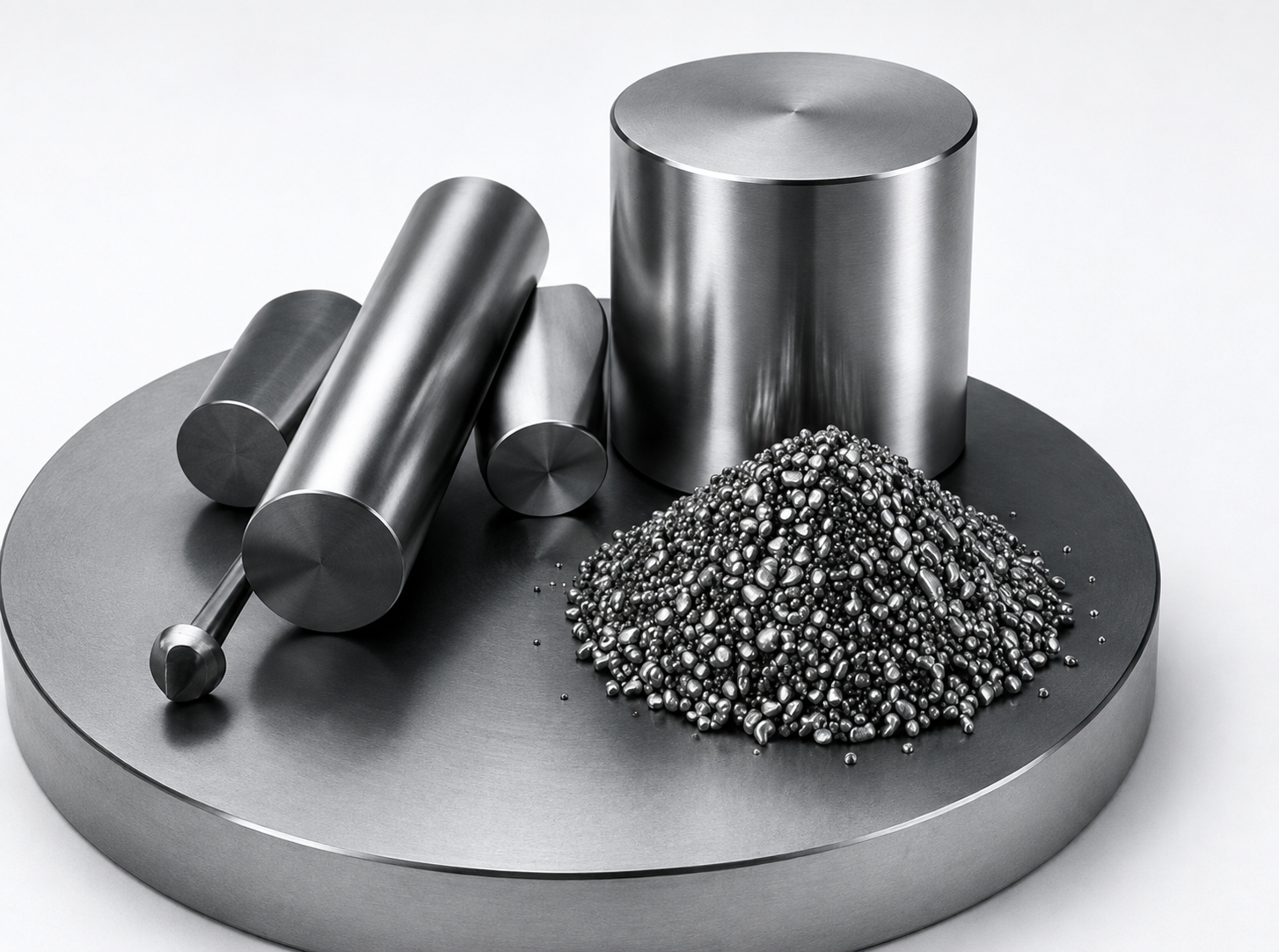
Adopt high-pressure or vacuum melting casting to ensure dense alloy structure and no air holes.
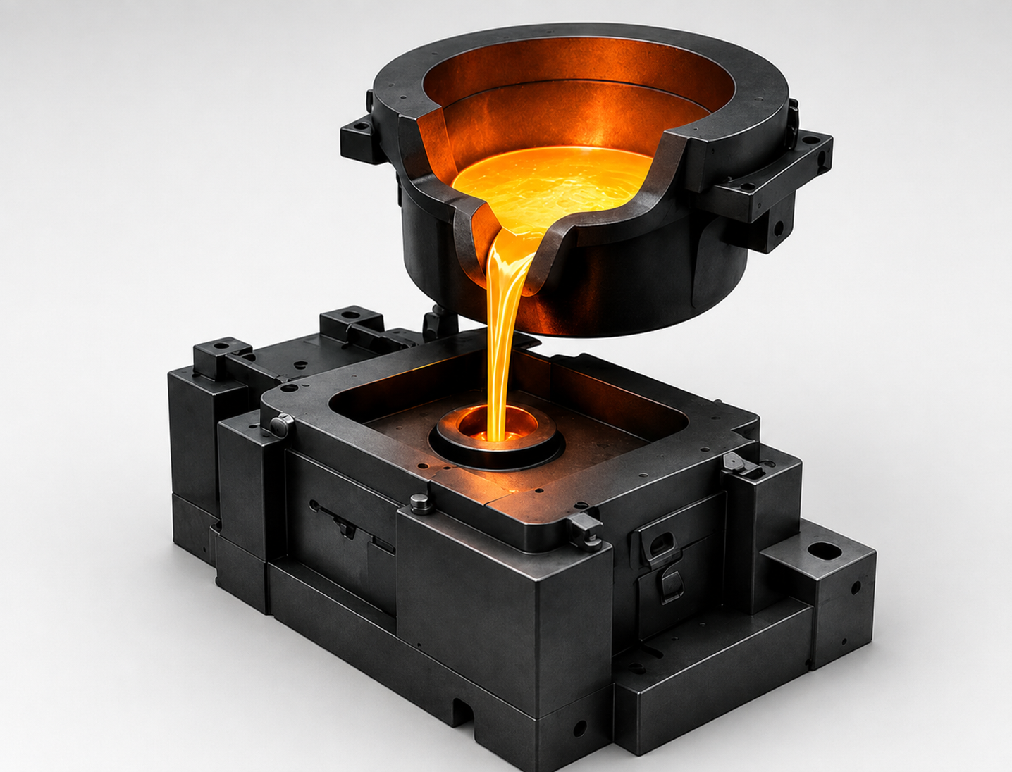
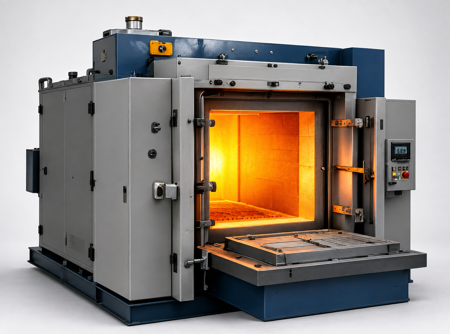
Perform annealing or isothermal treatment on the casting blank to eliminate internal stress and improve material stability.
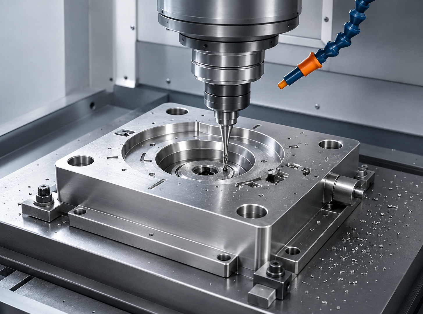
Use high-precision processing equipment to perform cutting, grinding and other processing on the mold.
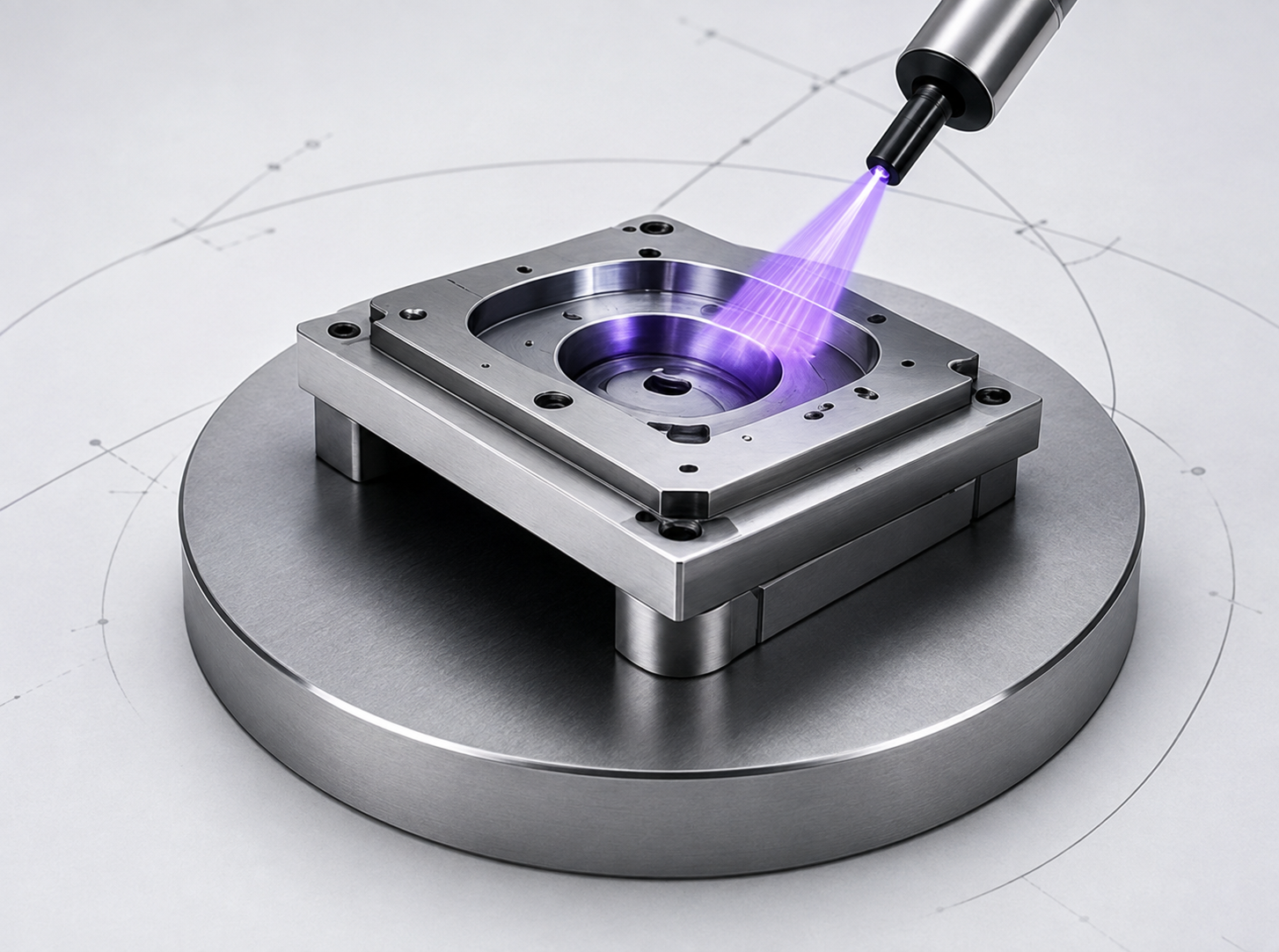
Carry out polishing, coating or surface strengthening treatment to improve surface hardness and wear resistance.
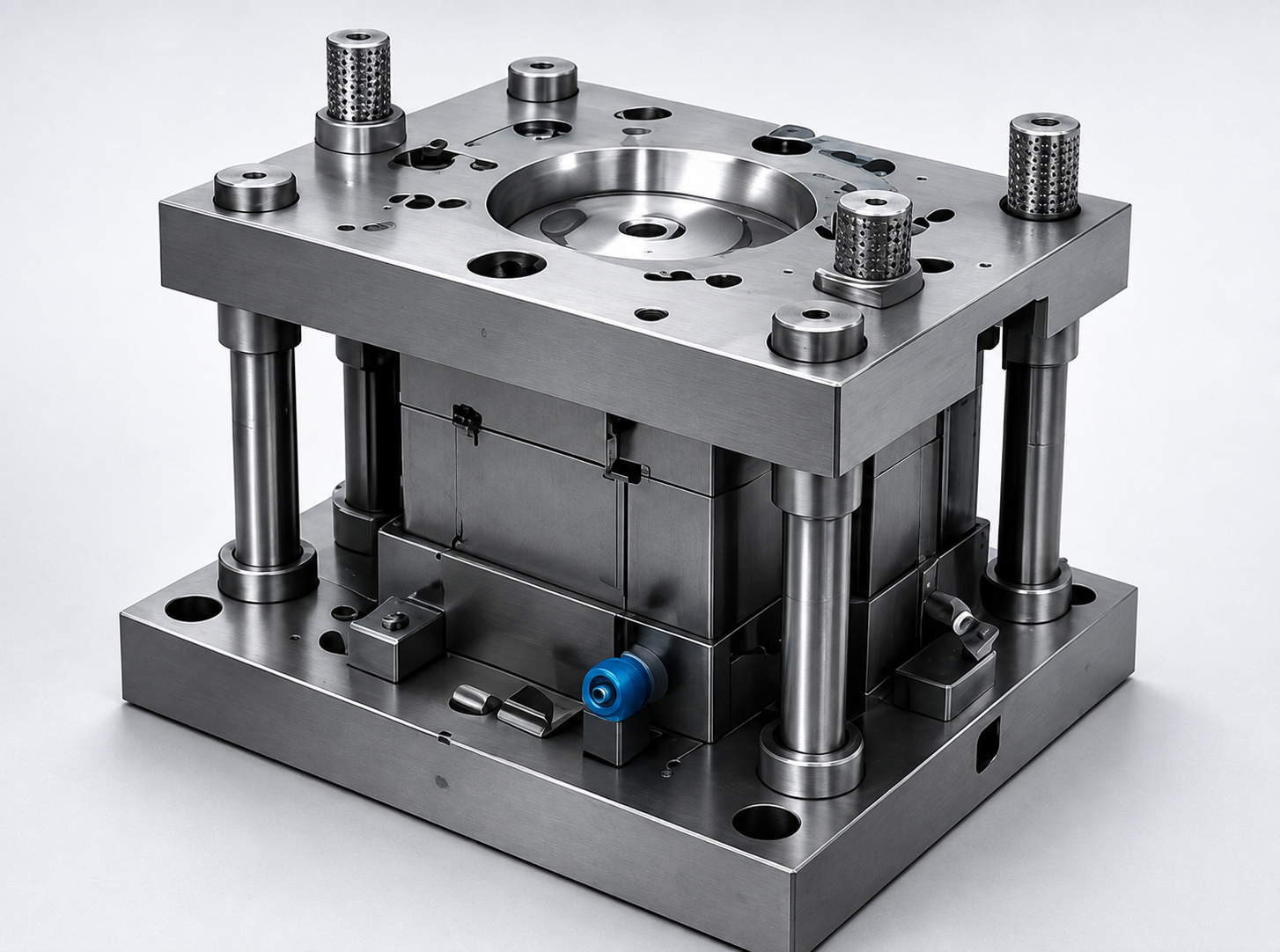
Precisely assemble and debug each part of the mold to ensure smooth movement and matching accuracy.
Conduct comprehensive inspection through CMM, hardness tester and other testing equipment to ensure the mold meets the design requirements.
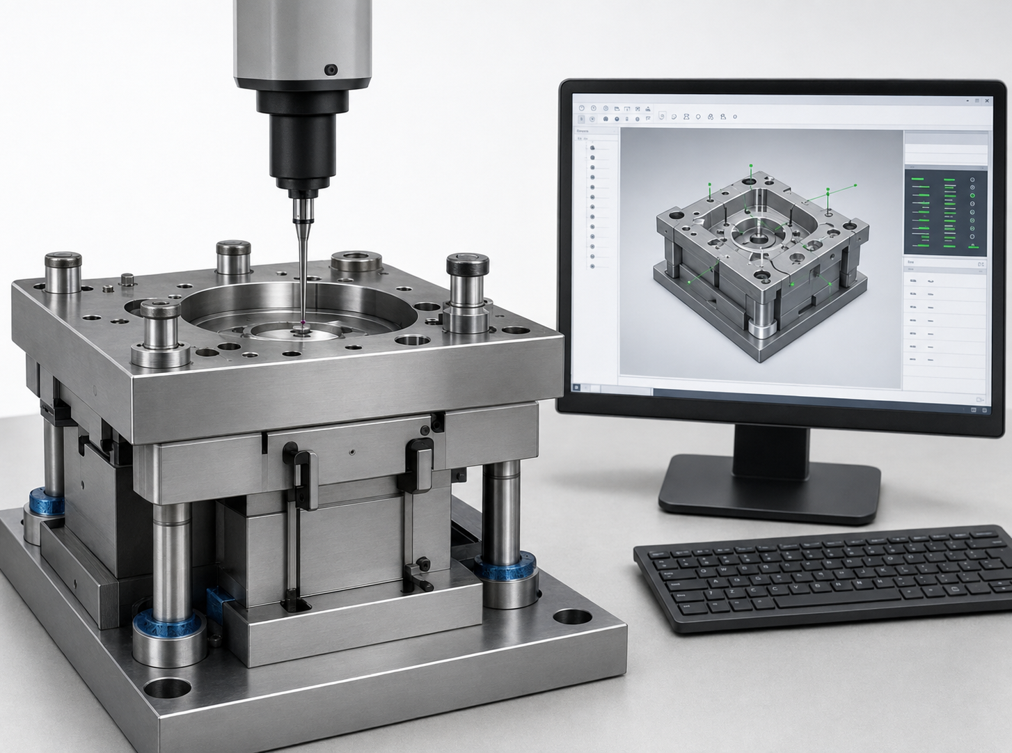
The mold structure must balance thermal management, flow control and precision requirements.
Using conformal cooling channels that closely follow the product contours
The cross-sectional area and layout density of the cooling channels are optimized through thermal flow simulation
Local cooling reinforcement structures are added in critical areas (such as gates and thick wall sections)
Avoid sharp corners and sudden turns, use a gradually changing cross-section flow channel
Ensure the gate position and quantity allow the melt to fill the cavity in a laminar flow state
Design overflow grooves to collect cold material and gas, preventing air entrapment
Appropriate draft angle (usually 0.5–1.5°) prevents tearing
Ejector elements are evenly distributed to avoid local stress concentration caused brittle cracking
If necessary, set up elastic ejection or air-assisted ejection
Match the mold material's thermal expansion coefficient with the shrinkage characteristics of the amorphous alloy
Reserve molding shrinkage (amorphous alloy shrinkage is about 0.2%–0.6%, depending on the composition)
These key indicators define the dimensional precision, surface quality, sealing performance, and thermal consistency required for reliable amorphous alloy molding.
| Accuracy Dimension | Typical Requirement Range | Function |
|---|---|---|
| Mold Cavity Size Tolerance | ±0.005 – ±0.01 mm | Directly affects product assembly and interchangeability |
| Flatness / Parallelism | ≤0.01 mm / 100 mm | Prevents warping of molded sheet or strip-shaped parts |
| Surface Roughness Ra | 0.05 – 0.1 μm (mirror grade) | Improves demolding, reduces surface streaks and air bubbles |
| Parting Surface Fit Clearance | ≤0.008 mm | Prevents flash and ensures vacuum system sealing |
| Cooling Channel Position Tolerance | ±0.05 mm | Ensures a uniform thermal field and avoids local crystallization |
Share your drawing, alloy system, tolerance requirements, and expected production volume with our engineering team.
In addition to dimensional accuracy, material selection, exhaust design, temperature control, and regular maintenance are essential for stable amorphous alloy molding.
Mold materials must maintain high thermal conductivity, fatigue resistance, impact resistance, and surface durability.
Efficient exhaust design removes trapped gases and supports complete, defect-free mold filling.
Stable and uniform mold temperature is critical for controlling cooling behavior and preventing local crystallization.
Preventive maintenance helps preserve mold accuracy, surface quality, thermal consistency, and long-term production stability.
The amorphous alloy blank is heated within its forming temperature range, pressed into the precision mold, and rapidly cooled to achieve the required geometry and surface quality.
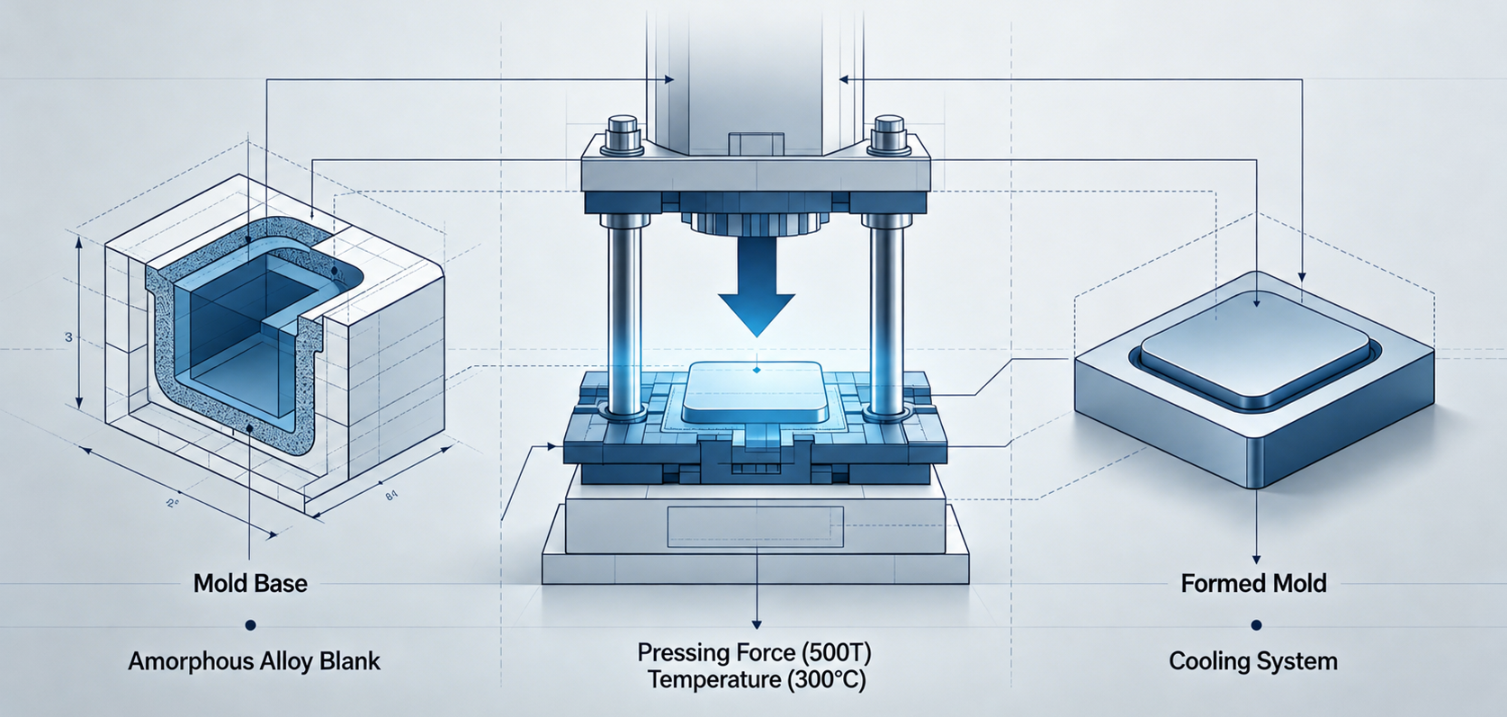
Each forming process places different demands on mold structure, thermal management, material flow, and part release.
| Processes | Mold design focuses on |
|---|---|
| Die casting (mainstream) | High vacuum sealing, high-speed filling, strong cooling |
| Thermoplastic molding | Uniform heating and cooling, low-friction demolding |
| Vacuum casting / spray casting | Small gates, extremely short flow channels, rapid heat exchange |
| 3D printing + mold inserts | Conformal cooling combined with local gradient materials |

Integrated support from mold design and precision manufacturing to process validation and production delivery.
Amorphous alloys must cool rapidly and uniformly to avoid crystallization. The mold therefore requires carefully controlled thermal conductivity, cooling-channel design, dimensional accuracy, surface quality, and exhaust performance.
Common routes include die casting, thermoplastic molding, vacuum casting or spray casting, and processes that combine 3D-printed structures with mold inserts. The mold design focus changes with the selected process and component geometry.
Evaluation can cover cavity-size tolerance, flatness, parallelism, surface roughness, parting-surface clearance, and cooling-channel position. Final requirements must be confirmed against the part design, alloy system, forming route, and inspection method.
Selection considers thermal conductivity, heat resistance, fatigue resistance, impact resistance, wear behavior, and compatibility with surface treatments such as PVD coating or nitriding.
Provide the component drawing or 3D model, alloy system, critical dimensions and tolerances, surface requirements, expected quantity, preferred forming process, and project schedule where available.
Share your component geometry, alloy system, target tolerances, production volume, and forming requirements. Our engineering team can evaluate mold structure, material selection, cooling strategy, and manufacturing feasibility.