MOLD CENTER SOLUTIONS

Tooling Materials for Amorphous Metal Molding

Mold material selection directly affects cooling rate, amorphous-structure retention, dimensional stability, surface quality, and tool life.

We evaluate copper alloys, tooling steels, tungsten-based materials, and advanced ceramics against the alloy system, part geometry, forming route, and production target.

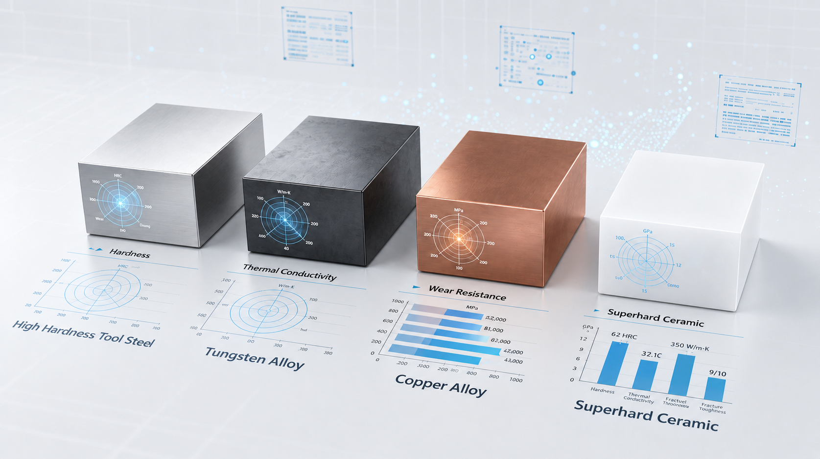
Comparison of tooling steel, tungsten alloy, copper alloy, and ceramic mold materials
DIRECT ANSWER

Why Mold Material Selection Matters

Amorphous alloys must cool quickly and uniformly to prevent local crystallization. The mold must therefore combine heat extraction, dimensional stability, surface durability, and resistance to repeated thermal shock.

No single mold material provides the best performance in every category. Production tools often combine a strong steel structure with high-conductivity inserts, wear-resistant local components, and engineered surface treatments.

COMMON MOLD MATERIALS

Common Materials for Amorphous Alloy Molds

Four commonly used mold material systems for different amorphous alloy forming requirements.

High-hardness tool steel mold
Tungsten alloy mold
Copper alloy mold
Superhard ceramic mold material
01 / HIGH-HARDNESS TOOL STEEL

High-Hardness Tool Steel

High-hardness tool steel is one of the most common materials used in amorphous alloy molds.

Main Features

  • High strength
  • Good wear resistance
  • Relatively high thermal stability
  • Easy to machine precisely
  • Relatively controllable cost

Applicable Scenarios

  • Medium and large structural components
  • High-pressure injection molds
  • Mass production

Limitations

  • Average thermal conductivity
  • Prone to thermal fatigue after long-term thermal cycling
  • Local cracks can develop easily
02 / TUNGSTEN-BASED MATERIALS

Tungsten Alloys and Tungsten Steel

Because amorphous alloys require extremely fast cooling rates, tungsten-based materials are often used in high-end molds.

Main Features

  • High hardness
  • High wear resistance
  • High melting point
  • Low thermal deformation
  • Excellent thermal stability

Advantages

  • Suitable for micro-precision parts
  • Can withstand rapid high-temperature cycles
  • Excellent dimensional stability

Limitations

  • Relatively brittle
  • Difficult to process
  • Relatively high cost

Common Applications

  • Microelectronic components
  • Medical devices
  • Microstructure molds
03 / COPPER ALLOY

Copper Alloy Materials

High-thermal-conductivity copper alloys are very important materials for amorphous alloy molds.

Common Materials

  • Beryllium copper
  • Chromium-zirconium copper
  • High-thermal-conductivity copper alloy

Main Functions

  • Rapid heat dissipation
  • Improved cooling efficiency
  • Shorter molding cycles

Advantages

  • Extremely high thermal conductivity
  • Can reduce the risk of local crystallization
  • Helps form a stable amorphous structure

Limitations

  • Low hardness
  • Easily worn
  • May deform during long-term use

Solutions

  • Use in combination with tool steel
  • Adopt an insert structure
  • Apply a hardened surface coating
04 / ADVANCED MATERIALS

Superhard Alloys and Ceramic Materials

Some high-end amorphous alloy forming processes use tungsten carbide, silicon nitride, or zirconia ceramics.

Common Materials

  • Tungsten carbide
  • Silicon nitride
  • Zirconia ceramics

Characteristics

  • Extremely high wear resistance
  • Excellent high-temperature stability
  • Strong corrosion resistance

Applicable Scenarios

  • Ultra-microstructure molding
  • Special precision applications
  • High-wear-resistance conditions

Limitations

  • Brittle
  • High processing cost
  • Difficult to repair
ENGINEERING COMPARISON

Material Selection by Use, Risk, and Prevention Strategy

Compare common mold materials based on their typical applications, production risks, and recommended preventive measures.

Mold Material Type Common Specific Materials Core Uses Common Problems in Production Solutions / Preventive Measures
Copper Alloy Chromium-zirconium copper, beryllium copper, and tungsten copper Mass-production cavities and high-conductivity inserts

1. Thermal fatigue and cracking: Rapid alternation between heating and cooling can generate internal stress and microcracks.

2. Wear and adhesion: The high hardness of amorphous alloys can wear the mold cavity, while adhesion may occur at high temperatures.

3. Insufficient strength: Copper alloys have lower strength than tooling steel and may deform in complex mold structures.

Optimized design: Improve cooling-system uniformity and reduce thermal stress.

Surface treatment: Apply PVD or CVD coatings such as CrN, TiAlN, or diamond-like carbon to improve surface hardness and resistance to adhesion.

Careful material selection: Use high-strength copper alloys for complex molds or evaluate the use of high-strength tooling steel.

Tooling Steel Hot-work tooling steel such as 8407 or DIEVAR, and stainless steel Mold frames, sliders, structural components, and high-durability or high-temperature forming cavities

1. Insufficient heat dissipation: Thermal conductivity is substantially lower than that of copper alloys, which may cause inadequate cooling and crystallization.

2. Thermal fatigue and cracking: Repeated thermal shocks may produce thermal-fatigue cracks.

Efficient cooling: Use conformal cooling channels to maximize cooling efficiency.

Controlled application: Use tooling steel when high mold strength or long tool life is required, together with an effective cooling system.

Surface strengthening: Apply nitriding or protective coatings to the mold cavity.

Silicon / Quartz / AAO Template Monocrystalline silicon, quartz, and porous anodic aluminum oxide (AAO) Laboratory research and development and micro/nano structure imprinting

1. Brittle and fragile: Uneven stress can easily cause fracture.

2. Demolding difficulty and contamination: Amorphous alloys may adhere to the template, and forced demolding can damage the microstructure.

Process control: Operate in a vacuum or inert atmosphere to prevent oxidation.

Coating treatment: Use anti-adhesion coatings to improve demolding.

Sacrificial mold: For difficult-to-demold micro/nano structures, use the template as a disposable consumable.

Amorphous Alloy Zr-based and Ni-based amorphous alloys Precision micro molds and mold replication

1. High-temperature softening: The mold material softens when processed in the supercooled-liquid region.

2. Crystallization risk: Improper heating or cooling may crystallize the mold material and cause failure.

Precise temperature control: Maintain the processing temperature between the glass transition temperature and crystallization temperature.

Rapid cooling: Cool rapidly after forming to retain the amorphous structure.

Special equipment: Operate under a protective atmosphere.

PRODUCTION RELIABILITY

Common Problems in the Production and Use of Amorphous Alloy Molds

Common production risks and corresponding engineering measures for reliable amorphous alloy mold performance.

01

Thermal fatigue cracking is one of the most common problems. Due to the mold continuously experiencing high temperatures, rapid cooling, thermal expansion, and thermal contraction, long-term cycling can easily lead to microcracks, surface cracking, and local chipping.

Solutions: Optimize mold materials by selecting materials with improved thermal fatigue performance such as modified steel, tungsten alloys, or powder high-speed steel.

Surface hardening treatments, including nitriding, DLC coating, and PVD coating.

Optimize the cooling system to avoid local overheating. Ensure uniform cooling channels, optimize thermal flow simulation, and employ a temperature monitoring system.

02

If the mold cools unevenly, the amorphous alloy will locally form crystals. Local crystallization can lead to product scrap. The consequences include: decreased strength, increased brittleness, and product performance failure.

Solution: Use high thermal conductivity copper alloy inserts and optimize the cooling circuit to improve mold thermal conductivity.

Improve cooling uniformity through CAE simulation, thermal flow field analysis, and injection path optimization.

03

Amorphous alloys are prone to sticking to the mold surface at high temperatures, which can lead to surface scratches, difficulty in demolding, and product defects.

Solution: Use high-quality surface treatments such as mirror polishing, DLC coating, and anti-adhesion coatings.

Optimize the demolding structure by adopting draft angles, venting designs, and runner structures.

04

Amorphous alloys have high strength, which causes greater wear on molds. The molds may experience excessive wear.

Especially in microstructure areas, gate areas, and under high-frequency production conditions, there is a tendency for dimensional drift and deterioration of surface roughness.

Solution: Use highly wear-resistant materials such as tungsten steel, powder high-speed steel, and superhard alloys.

Apply surface hardening techniques such as PVD, CVD, and nitriding treatment.

05

After long-term production, the mold may experience dimensional drift due to thermal deformation, resulting in reduced dimensional stability.

This can lead to products exceeding tolerance limits and decreased batch consistency.

Solution: Optimize the mold structure by using a symmetrical design, thermal compensation design, and zoned cooling system.

Use high-precision machining methods such as five-axis CNC, precision grinding, and online inspection systems.

TECHNICAL INQUIRY

Need to Confirm Mold Accuracy for Your Component?

Share your drawing, alloy system, tolerance requirements, and expected production volume with our engineering team.

Send an Inquiry
FULL-PROCESS CONTROLS

Risks That Extend Beyond the Mold Material Itself

Tool performance also depends on melt handling, demolding, multi-material interfaces, and thermal management throughout production.

01

Melt Debris & Oxidation

Splashed metal can damage the cavity during closing or introduce oxide inclusions that reduce product purity.

Recommended Controls
  • Optimize pouring and sprue design to reduce splashing
  • Use inert-gas cleaning before pouring and mold closing
  • Maintain vacuum or inert-gas protection for reactive Zr- and Ti-containing alloys
02

Demolding & Ejection Damage

High strength, insufficient draft, or an unbalanced ejector system can scratch, puncture, deform, or crack the component.

Recommended Controls
  • Provide approximately 1°–3° draft where geometry permits
  • Target mirror-level cavity finish, such as Ra ≤ 0.1 μm
  • Distribute ejector pins or plates evenly and control ejection temperature
03

Galvanic Corrosion

Dissimilar inserts can create electrochemical corrosion at humid interfaces, leading to loosening or visible corrosion.

Recommended Controls
  • Apply insulating and corrosion-resistant interface treatments
  • Use micro-arc oxidation, nickel plating, protective paint, or resin barriers as appropriate
  • Reduce direct contact area or select materials with closer electrode potentials
04

Tolerance & Precision Loss

Thermal-expansion mismatch and uneven cooling can cause warpage and reduce dimensional accuracy or assembly fit.

Recommended Controls
  • Use coupled flow and thermal simulation during mold design
  • Combine conformal cooling with multi-point temperature sensing and zoned control
  • Validate shrinkage through simulation or trials and compensate cavity dimensions

Successful amorphous-alloy tooling is a continuous balance: achieve extremely rapid, uniform cooling and prevent oxidation while maintaining mold life, heat-transfer efficiency, surface integrity, and final dimensional accuracy.

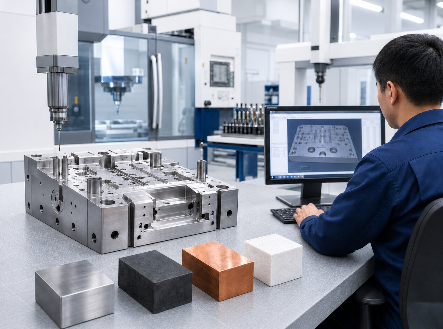
Material selection, precision inspection, and engineering validation for amorphous alloy molds
MATERIAL ENGINEERING CAPABILITY

From Material Selection to Stable Mold Performance

Engineering support for selecting, combining, and validating mold materials according to cooling performance, tool life, part geometry, and production requirements.

  • 01 Mold material and application requirement evaluation
  • 02 Thermal conductivity, strength, and wear analysis
  • 03 Insert structure, surface treatment, and cooling design
  • 04 Prototype testing and production-performance validation
MOLD MATERIALS FAQ

Questions Engineering and Sourcing Teams Ask

Which mold material is best for amorphous alloy production?

There is no universal best material. Copper alloys prioritize cooling, tooling steels provide structure and durability, tungsten-based materials resist wear and deformation, and ceramics serve specialized high-precision conditions. Hybrid mold structures are often the most practical solution.

Why are copper-alloy inserts commonly used?

Their high thermal conductivity helps remove heat rapidly and uniformly, reducing local crystallization risk and shortening the molding cycle. Because copper alloys have lower hardness, they are often supported by steel and protected with surface treatments.

How can thermal-fatigue cracking be reduced?

Material selection, uniform cooling-channel design, thermal-flow simulation, temperature monitoring, and surface hardening all contribute. The correct combination depends on forming temperature, cycle rate, and local geometry.

When should ceramics or superhard alloys be considered?

They are candidates for ultra-fine structures, high-temperature stability, severe wear, and special precision applications. Their brittleness, processing cost, and repair difficulty must be evaluated early.

What project information is needed for material selection?

Share the alloy system, part drawing or 3D model, critical dimensions, surface requirements, expected volume, forming process, cycle target, and tool-life expectations.

REQUEST A QUOTE

Discuss Your Mold Material Requirements

Share your alloy system, component geometry, target tolerances, production volume, and forming conditions. Our engineering team can evaluate material combinations, cooling performance, coatings, and tool-life requirements.